Quantcast
Channel: ZR6AIC
Viewing all 69 articles
Browse latest View live

Setting up the Kydera DM-880 Portable DMR (mototurbo)

$
0
0

Setting up the Kydera DM-880 Portable DMR (mototurbo)


Here is the instructions to setup the Kydera DM-880 to connect to the Amateur radio repeater network in South Africa.
What do you get with the Kydera DM-880 (Programming cable is optional)

How to Program the DM-880
You can download the Programming software here.
Here is the video how to install the Programming software.

Unzip the downloaded file and run the 
Here is a video on how to program the Kydera DM-880


Here is the Configuration file with the South Africa DMR Repeaters and Analog repeaters pre-configured mentioned in the video above.


How to Decode DMR-MARK (mototurbo) with SDRsharp and rtl dongle on Windows 7

$
0
0

How to Decode DMR-MARK (mototurbo) with SDRSharp and RTL dongle on Windows 7

DSD decoding with SDRSharp and RTL dongle.


I found this website with very nice plugins for your SDR# software
http://rtl-sdr.ru/page/vse-dostupnye-na-etom-sajte-plaginy-s-kratkim-opisaniem (you can use this script to install all the plug-ins) http://rtl-sdr.ru/uploads/download/sdr-update.zip
Here is the list of plugins

  1. Audio Processor Displays range of audio signal contains 6 adjustable bandpass filters and customizable deemfazis filter.
  2. IF Processor Displays range IF signal to the demodulator, an asymmetric bandpass filter and a custom tracking notch filter.
  3. Base band Recorder Writes the entire IQ stream received from the tuner to a file, you can choose a folder to store the recordings, and there is a scheduler for recording time. Large buffer for recording flow with high sampling rate without any losses. It can be controlled from other plug-ins.
  4. IF Recorder Writes a stream of IQ intermediate frequency to a file, you can choose a folder to store the recordings, and there is a scheduler for recording time. It can be controlled from other plug-ins.
  5. Audio Recorder Writes the audio file. Ample opportunities to control the format of the output file (mono, stereo, bit rate, sample rate). Extensive records management (do not write in the absence of a signal, create new files when changing frequency, etc.). Customizable file and folder names.
  6. Decoder CTCSS squelch It displays the CTCSS tone in the presence of the signal and provides the squelch responds to set the tone.
  7. DCS Decoder Squelch Displays DCS codes in the presence of a signal and contains a squelch responsive to certain code or the presence of any code in the signal.
  8. AUX VFO Adds additional radio channels to SDR #. You can add more than one radio channel.
  9. DSD Interface The plug consists of three parts. The first - an additional audio output from the demodulator can be used to output the audio signal through a virtual audio cable to other programs (WXtoImage, DSD, etc.). The second - a graphical interface to configure and run a digital signal decoder DSDPlus. And the third - to automatically turn off the sound output SDR # when choosing a frequency with a digital signal.
  10. Time Shift It creates a memory buffer of up to several minutes. You can listen to the signals that have been broadcast and a present in the buffer. "All that is visible on the waterfall can be heard."
  11. Digital Audio Processor It contains audio bandpass filter squelch by the presence of an audio signal and a signal scrambler inversion spectrum.
  12. DDE Tracker + Scheduler Plug-in to communicate with the satellite tracking programs (Orbitron, WXTrack, SatPC32). When / companion care in the reception area is executed a list of commands for the satellite specified in the scheduler. It can control other plug-ins and run external programs.
  13. QPSK Demodulator Plug-in for QPSK demodulation signal from the Russian satellite Meteor-M2 in real time. The final signal may be recorded in a file or transmitted via TCP on special version LRPTDecoder for decoding in real time. It may interact with other plug-ins.
  14. TV The plugin displays the received PAL / SECAM TV signal. For receivers with a bandwidth of more than 7 MHz at the same time you can listen to the sound via the main radio SDR #. For rtl-sdr receivers need the modified file rtl-sdr.dll.
  15. Frequency Manager Modified standard frequencies Manager SDR #. Added scanner iterates through the selected frequency. Added Manage window manager and some other improvements.
  16. Frequency Scanner Fast scanner. It scans the specified frequency range. Saves frequency are not in the manager and activity time at these frequencies. It can scan multiple bands with different grid spacing, modulation bandwidth of the signal. There are modes of scanning all frequencies in the range, or only frequencies which are in the frequency or vice versa manager only frequencies that are not in the manager.
  17. MPX Output It displays the selected audio device MPX signal after WFM demodulator with sample rate conversion to 192 kHz for further processing in other programs (eg RDSSpy).
  18. Avia band 8.33 calculator Corrects manual input frequency range of air according to the standard steps for 8.33 kHz.
  19. IQ Correction This is analogous to the standard functions of SDR # IQ correction. For slower computers help save some CPU time. There is a separate mode for R820T tuners - removal of only a constant component correction IQ on these tuners are required.
  20. Audio Waterfall This plug-in created by Kiriyama. Adds SDR # waterfall displays the spectrum of the audio signal.21) Frequency LockThe function of this plugin is very simple, it blocks the frequency change settings in SDR #. Written at the request of the user to avoid accidental change of frequency of administration.

Here is a short description of the steps I took to install the SDRSharp plugins.
  1. Firstly you need to install the SDRSharp software. Here is a link how to do that http://giga.co.za/smf/index.php/topic,34.0.html
  2. Then Download the Plugin script from here. http://rtl-sdr.ru/uploads/download/sdr-update.zip
  3. Unzip the sdr-update,zip file in the directory where you have installed the SDRSharp.exe in step 1.
  4. Then unzip should create a directory sdr-update in the directory where the SDRsharp.exe file was unzipped.
  5. There should be 3 files in the sdr-update directory. (httpget.exe,setup.bat and unzip.exe) (dir)
  6. Make sure you have internet connection.
  7. Then run the setup.bat file in the directory.
  8. You will be asked some questions to override some installations and configurations, always say Y
  9. Download and unzip DSDPlus application in any directory of your choice for from here http://www.dsdplus.com/download/dsdplus/DSDPlus1p074.zip mite have to change version number if there is a newer one available.
  10. Create a start_dsdplus.bat file using Notepad  in the directory where you unzipped the DSDPlus1p074.zip zip file.
  11. For now enter the following in the bat file with Notepad DSDPlus.EXE -i1 -o2 -fr
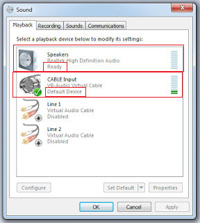
  12. Set the playback device as follows making the VB-Cable the default device and Speaker just ready.
  13.  Set the recording settings as follows. (Set VB-Cable as default and Stereo Mixer as ready)
SET VB-Cable as default and Stereo Mixer as ready.

14) In the Recording tab set the VB-Cable as default device and Stereo Mixer ready.
15) Set the sound levels as follows.
set cable volume not to high

16) Now run the start_dsdplus.bat file that you created in step 3 and check that the numbers correspond to the red in the pictures below.
17)  i = Audio input to DSDPlus and o = Audio Output from DSDPlus
18) Input to DSPPlus must be from VB-Cable and not any other device (Stereo mixer in my case).
19) Output must go to Speakers in my case to 2 
20)Your Audio input and output configuration should be different to the one I have.
21) You will then need to change it in the start_dsdplus.bat file and then re run start_dsdplus.bat file.
22) If your Audio Input and Output configuration is correct you will have to just set your audio levels coming from SDRSharp and going to speaker.

Your sound card numbers will be different and you need to update the bat file
24. Now we need to configure the DSD plugin in sdrSharp by giving it the path to your DSDPlus.
enter the path to your DSDPlus.exe in the DSD path block shown below. Now change the Audio settings in SDRSharp dsd plugin to be the same as as we did in the batch file by changing the audio device number.

Change input and output audio device as we did in batch file.
26) Now select the VB-Cable option in the SDRSharp DSD plugin menu to point to the VB-Cable

27) Then tune to DMR frequency channel  in your area with SDRsharp at the top frequency selection and start the DSD on the left menu.
I then got this warning pop box hidden behind my SDRSharp. Just click Run and the DSD popups will appear.

If all went right the following Scope,log and channel activity popups will appear.


Final check that the correct VB-Cable is used for Audio input and speaker as output.

28) For best results, make sure that all your SDR# and  VB-cable / VAC sample rates are set to 48kHz and that you have disabled “Filter Audio” in SDR#. Also, the audio volume of SDR# should not be set to high.
29)Here is a list of DMR frequencies in South Africa


30)Here is the list of repeater frequencies for DMR in South Africa http://zs6ro.org/index.php/dmr-repeaters/dmr-za-repeater-list
If all when ok you should be able to hear the decoded audio.
Hope this help.
Let me know if you get stuck by adding comments at the bottom..

Decoding DMR (mototurbo) from webSDR http://zr6aic.giga.co.za:8902 using DSDPlus 1.7 and VB-cables on Windows 7

$
0
0

Decoding DMR (mototurbo) from webSDR http://zr6aic.giga.co.za:8902 using DSDPlus 1.7 and VB-cables on Windows 7


Screenshot of working DMR
1) Install VB-cable from http://vb-audio.pagesperso-orange.fr/Cable/index.htm
3) Create a start_dsdplus.bat in the directory where you unziped the DSDPlus1p074.zip zip file.
4) For now enter the following in the bat file DSDPlus.EXE -i1 -o2 -fr
5) Set the playback device as follows making the VB-Cable the default device and Speaker just ready.


6) Set the recording settings as follows.


7) In the Recording tab set the VB-Cable as default device and Stereo Mix ready


8) Set the sound levels as follows.
VB-Cable level about 10% and Speaker level.


9) Volume settings
Volume Settings.
10) Now run the start_dsdplus.bat file that you created in step 3 and check that the numbers correspond to the red in the pictures below.
 i = Audio input to DSDPlus and o = Audio Output from DSDPlus
10.1) Input to DSPPlus must be from VB-Cable and not any other device (Stereo mixer in my case).
10.2) Output must go to Speakers in my case to 2.
10.3) Your Audio input and output configuration should be different to the one I have.
10.4) You will then need to change it in the start_dsdplus.bat file and then re run start_dsdplus.bat file. and refresh websdr website (CTRL F5)
Then re-tune websdr DMR frequency to 438.225Mhz FM
11) If your Audio Input and Output configuration is correct you will have to just set your audio levels coming from webSDR and going to speaker.

DSDPlus command shell details

12) Then go to my WEBsdr in your Chrome or Firefox  browser http://zr6aic.giga.co.za:8902


Select 70cm_dmr band and tune frequency to 438210.88 Fm
13) There is small burst of data with now sound wait for the long bursts of data witch is normally conversation. I think the small burst is just data and you will not hear anything.
(Sound level to DSDPlus input should not be to strong)

Hope this help.

I will add some videos tomorrow.


Video 1


What can I do with the TP-Link TL-WR703N router? (APRS, SDR)

$
0
0
What can I do with the TP-Link TL-WR703N router? (APRS, SDR)


Basically this device is meant to be a little 3g travel router. You can plug in a 3g USB adapter and share that Internet connection to multiple devices over WIFI. It also supports Ethernet. It runs a Linux operating system so this opens up lost of Amateur Radio opportunities. So for $24 you can get a 400mhz Linux computer, with Ethernet, Wifi and USB ports and several GPIO pins.
This router is available from http://www.giga.co.za/ocart/index.php?route=product/product&path=99&product_id=150

1) SDR
Using a RTL-SDR dongle on TL-WR703n you can listing to Amateur radio frequencies.
If you’re running OpenWrt Barrier Breaker (i.e. trunk) you can install librtlsdr SDR dongle labraries
Here is the pre compiled applications
https://steve-m.de/projects/rtl-sdr/openwrt/packages/

2) APRS
This unit can be used to do APRS with external GPS unit.
More info how to make this router a (APRS) Igate go  to http://www.aprs4r.org/cgi-bin/trac.cgi/wiki/OpenWrtAPRS4RInstallation
The router is well documented http://wiki.openwrt.org/toh/tp-link/tl-wr703n/pcb

Geostationary AMSAT Satellite (Phase 4) Spacecraft Covering the hole of Africa and Europe. (P4B)

$
0
0
I think this Satellite will open up one of the most exiting telecommunication capabilities for Africa and Europe.(P4A/B)

Coverage map
Phase 4 AMSAT planed

Planned Frequency.

This satellite will have two linear transponders. (250 Khz and 8Mhz wide)
Narrowband transponder:
Uplinks: 2400.050-2400.300 MHz
Downlinks: 10489.550- 10489.800 MHz

Wideband transponder:
Uplinks: 2401.500 – 2409.500 MHz
Downlinks: 10491.000 -10499.000 MHz 

It will be so nice to have fixed antennas mounted on mast pointing to the satellite having continuous communication to any where in Africa and Europe. HI ;-) ;-)

Will have to start looking for some equipment and antennas for this one.

More information http://amsat-uk.org/2015/07/03/phase-4-spacecraft-frequencies/

Half Wave Dipole Calculator

How setup your NWT Spectrum Analyzer on Linux. (Ubuntu)

$
0
0

How setup your NWT Spectrum Analyzer on Linux. (Ubuntu).


NWT70 in picture.

I got my Spectrum Analyzer and here are the steps I use to install and configure it on my Linux (Ubuntu) laptop.

Download the software here. http://www.dl4jal.eu/  link to the file http://www.dl4jal.eu/linnwt4_V4_11_10.tar.gz

Copy the file to your favorite directory
mkdir nwt
cd nwt
cp /home/anton/Downloads/linnwt4_V4_11_10.tar.gz  ./
Unzip the file in the directory.
unzip linnwt4_V4_11_10.tar.gz
Check if the files has unziped
There should be a directory linnwt4_V4_11_10 and cd to it.
cd linnwt4_V4_11_10
Check if you have qmake installed
qmake -v
 You need vertion QT 4 + if you don't have it, install it.
sudo apt-get install build-essential
now install QT
sudo apt-get install gcc qt4-qmake libqt4-dev
now create a directory build inside the linnwt4_V4_11_10 directory
mkdir build
Change to the build directory
cd build
run the gmake command
qmake -qt4 ../
Then run the make command
make
Get coffee ;-) it takes 2 min
There should the be a new file in exsiting directory called linnwt.
Connect your spectrum analizer to your laptop USB connector.
then run the apllication linnwt
sudo ./linnwt
mmmmm, its German!
no problem, run it with this parameter to get it in Englesh
sudo ./linnwt ../app_en.qm

USB device error could not find your NWT device.
So how do I identify my USB device and configure it in the software ?

Run the command tail -f /var/log/syslog


Then unplug your spectrum analyzer usb cable from laptop and reconnect it after 2 seconds to laptop.

There will be new text appearing in the terminal console. Something like this below.

Jun 26 11:55:07 anton-SATELLITE-P755 kernel: [51330.537093] usb 2-1.2: USB disconnect, device number 5
Jun 26 11:55:07 anton-SATELLITE-P755 kernel: [51330.537573] ftdi_sio ttyUSB0: FTDI USB Serial Device converter now disconnected from ttyUSB0
Jun 26 11:55:07 anton-SATELLITE-P755 kernel: [51330.537628] ftdi_sio 2-1.2:1.0: device disconnected
Jun 26 11:55:10 anton-SATELLITE-P755 bluetoothd[800]: Authentication attempt without agent
Jun 26 11:55:10 anton-SATELLITE-P755 bluetoothd[800]: Access denied: org.bluez.Error.Rejected
Jun 26 11:55:11 anton-SATELLITE-P755 kernel: [51334.756112] usb 2-1.2: new full-speed USB device number 6 using ehci-pci
Jun 26 11:55:11 anton-SATELLITE-P755 kernel: [51334.855421] usb 2-1.2: New USB device found, idVendor=0403, idProduct=6001
Jun 26 11:55:11 anton-SATELLITE-P755 kernel: [51334.855430] usb 2-1.2: New USB device strings: Mfr=1, Product=2, SerialNumber=3
Jun 26 11:55:11 anton-SATELLITE-P755 kernel: [51334.855434] usb 2-1.2: Product: FT232R USB UART
Jun 26 11:55:11 anton-SATELLITE-P755 kernel: [51334.855437] usb 2-1.2: Manufacturer: FTDI
Jun 26 11:55:11 anton-SATELLITE-P755 kernel: [51334.855440] usb 2-1.2: SerialNumber: AL01PTLP
Jun 26 11:55:11 anton-SATELLITE-P755 kernel: [51334.858330] ftdi_sio 2-1.2:1.0: FTDI USB Serial Device converter detected
Jun 26 11:55:11 anton-SATELLITE-P755 kernel: [51334.858406] usb 2-1.2: Detected FT232RL
Jun 26 11:55:11 anton-SATELLITE-P755 kernel: [51334.859036] usb 2-1.2: FTDI USB Serial Device converter now attached to ttyUSB0
Jun 26 11:55:12 anton-SATELLITE-P755 mtp-probe: checking bus 2, device 6: "/sys/devices/pci0000:00/0000:00:1d.0/usb2/2-1/2-1.2"
Jun 26 11:55:12 anton-SATELLITE-P755 mtp-probe: bus: 2, device: 6 was not an MTP device

You will be looking for ttyUSB?? in the text.

I my example, my usb was ttyUSB0

So now enter your ttyUSB?? in this usb port detail screen below. and then save your configeration.

Select the Settings > Options Menu from the pulldown menu in LinNWT4 application.

Change the value to /dev/ttyUSB?? Your port number found above.
In my case it was /dev/ttyUSB0

O.k., lets now setup a Frequency Spectrum scan.

Add frequency svan limits and then select a single or continuos scan option.

Connect your filter or circuit for testing on SMA terminals.

Then click on your Graphics display to see the return loss of you filter or circuit under test.

Scan display.
Hope this helps.
This spectrum Analizer is available from Giga Technology http://www.giga.co.za/ocart/index.php?route=product/product&product_id=226

Satellite recording of the SWAYAM Satellite on 25 Jun 2016 at 19:47GMT


OpenWebRX with KiwiSDR covering the whole HF band 0 -30Mhz is now up and running in South Africa

OpenWebRX with KiwiSDR covering the whole HF band 0 -30Mhz is now up and running in South Africa

$
0
0

OpenWebRX SDR covering the whole HF band 0 - 30Mhz  is now up and running in South Africa

This Web based SDR http://zr6aic.giga.co.za:8073 is using the new KiwiSDR Hardware running on Beagle bone.

KiwiSDR using OpenWebRX running on Beagle.
This Web based SDR is covering the Whole HF band 0- 30Mhz. here is the link go and check it out.

Here is the list of receivers around the world using the OpenWebRx platform.

http://sdr.hu/
Here is the list of OpenWebRX servers around the world.

http://sdr.hu/

The KiwiSDR will soon be available from Giga Technology. http://www.giga.co.za


How do you build a 1U Cube-Sat Linear transponder using SDR / DSP technology with limited Power?

$
0
0

How do you build a 1U Cube-Sat Linear transponder using SDR / DSP technology with limited Power?


Requirements:

Satellite requirements.
  1. Linear Transponder 70cm (437Mhz) up-link and S band (2.4GHz or 1.2Ghz down) Down-link (Bandwidth ? 250Khz on 70cm ?)
  2. Satellite Low Earth orbit (LEO) altitude between 160 ---? kilometers. We need this so we can calculate path loss and RF power and antenna gain requirements.
  3. Available Power ? from Solar panels and battery system ?
  4. Power left ? for transponder after OBC and stabilizer power ?
  5. Telemetry mode? CW / AX25 / AFSK 9k6 /....
  6. Satellite antennas for 70cm ? and (Polarization ?) 
  7. Satellite antennas for 2.4Ghz / 1.2Ghz and (Polarization ?) 
  8. Telemetry Requirements ? (ID, Temperature, Power in, Power out, Battery left, Transponder Mode status, Antenna Status, Satellite Orientation, ........)
  9. Inter board Connector Specification (PC/104 ?)
  10. OBC, SOLAR,charger,Orientation and Battery from existing Satellite ?
  11. 1 U Cube-Sat Space frame from existing Satellite (10x10x10) 1kg
  12. DSP 10 to 14Bit A/D /D/A Dynamic range. what is good enough ?
  13. PCB Board size details ?
  14. Space frame and Solar panel frame and Antenna deployment. (out of scope)
  15. Solar panels. (Out of Scope)
  16. Power regulator and Charge regulator and Battery. (out of Scope)
  17. Orientation controls. (out of scope)
  18. RF Linear Transponder using SDR / DSP. (70cm up 2.4Ghz or 1.2Ghz down)
  19. OBC (In scope ARM M4 or possibly A9)
  20. Inter board communication standard ?

Out of Scope for now:


  1. Space frame, Solar panels and panels frame.
  2. Solar panels
  3. Power regulator and Charge regulator and Battery.
  4. Orientation controls.
In scope for now:

  1. Linear Transponder using SDR / DSP. (ARM Processor possibly not FPLG due to power constraint.)
  2. Telemetry TX
  3. Command control RX

Block diagram.


Transponder SDR transmitter.

I will still add details here.
?

Transponder SDR receiver .

I will still add details here.
?

Ref :
TX

  1. https://github.com/F5OEO/rpitx
  2. http://ebrombaugh.studionebula.com/radio/txdac/index.html
  3. https://www.etherkit.com/rf-modules/si5351a-breakout-board.html
  4. http://www.simplecircuits.com/files/Download/QEX_release.pdf

RX

?

Possible def tools.

  1. GNU radio
  2. Math lab
  3. ARM DEV board tools.

SDR Comparison

$
0
0

SDR Comparison

Name TypeFrequency rangeBand withChannelsHost InterfaceWindowsLinuxMacEsitmated price
AirSpy Pre-build 24-1750 MHz 20 MSPS MSps ADC sampling, up to 80 MSPS for custom applications 0/1 USB Yes Yes Yes using ports US$199
SDRstick UDPSDR-HF1 Pre-built 0.1–30 MHz 80 Msps 0/1 1G Ethernet via BeMicroCV-A9 Yes Yes Yes US$169
Apache Labs ANAN-10E Pre-built 10 kHz – 55 MHz 122.88 Msps (14 bit ADC) 0/2 Gigabit Ethernet Yes Yes Yes US$995
Apache Labs ANAN-10/100 Pre-built 10 kHz – 55 MHz 122.88 Msps (16 bit ADC) 0/4 Gigabit Ethernet Yes Yes Yes US$1,649-US$2,449
Apache Labs ANAN-100D/200D Pre-built 10 kHz – 55 MHz 122.88 Msps (16 bit ADC) 0/7 Gigabit Ethernet Yes Yes Yes US$3,299-US$3,999
SunSDR2 Pre-built 10 kHz – 160 MHz 160 MSPS 3/4 10/100 Ethernet, WLAN (embedded) Yes Yes  ? US$1,960
bladeRFPre-built 300 MHz - 3.8 GHz 80 kSPS - 40 MSPS
RX/TX (12-bit ADC/DAC)
 ? USB 3.0 SuperSpeed Yes Yes Yes US$420
FLEX-6700 Pre-built 0.01–73, 135-165 MHz 245.76 MSPS (transceiver) 8/8 Ethernet Yes Yes Yes US$7,499
FLEX-6700R Pre-built 0.01–73, 135-165 MHz 245.76 MSPS (receiver) 8/8 Ethernet Yes Yes Yes US$6,399
FLEX-6500 Pre-built 0.01–73 MHz 245.76 MSPS (transceiver) 4/4 Ethernet Yes Yes Yes US$4,299
FLEX-6300 Pre-built 0.01–54 MHz 122.88 MSPS (transceiver) 2/2 Ethernet Yes Yes Yes US$2,499
FLEX-5000A Pre-built 0.01–65 MHz 48, 96, 192 kHz (transceiver) 2/2 1394a Firewire Yes No No US$2,800
FLEX-3000 Pre-built 0.01–65 MHz 48, 96 kHz (transceiver) 1/1 1394a Firewire Yes No No US$1,700
FLEX-1500 Pre-built 0.01–54 MHz 48 kHz (transceiver) 1/1 USB Yes No No US$650
Perseus Pre-built 10 kHz – 40 MHz (87.5–108 MHz using FM down-converter) 80 MSPS  ? USB Yes Yes ? US$1,199
SDRplay: Radio Spectrum Processor Pre-built 0.1–2,000 MHz 0.5-12 MS/s and up to 8 MHz bandwidth 0/1 USB Yes Yes Yes US$149
ISDB-T 2035/2037 Pre-built 50–960 MHz 0.5-12 MS/s and up to 8 MHz bandwidth 0/1 USB Yes Yes Yes US$25
Soft66AD / Soft66ADD / Soft66LC4 / Soft66RTL Pre-built 0.5–70 MHz External ADC required (I/Q output) 0/1 USB Yes Unofficially  ? US$20
FUNcube Dongle Pre-built 64–1700 MHz 96 kHz 0/1 USB Yes Yes Yes US$160
FUNcube Dongle Pro+ Pre-built 0.15–240 MHz, 420-1900 MHz 192 kHz 0/1 USB Yes Yes Yes US$200
FiFi-SDR Pre-built 200 kHz – 30 MHz 96 kHz (integrated soundcard) 0/1 USB Yes Yes  ? €120
SDR-IQ PnP 0.1 kHz – 30 MHz 66.666 MHz 1/1 ? USB Yes Yes Yes US$525
WinRadio WR-G31DCCPre-built 9 kHz – 50 MHz 100 MSPS 3/3 USB Yes NoNoUS$950
USRP B200Pre-built 70 MHz to 6 GHz 56 Msps  ? USB 3.0 Yes Yes Yes US$675
USRP B210 Pre-built 70 MHz to 6 GHz 56 Msps  ? USB 3.0 Yes Yes Yes US$1,100
USRP N200 Pre-built DC to 6 GHz 25 Msps for 16-bit samples; 50 Msps for 8-bit samples  ? Gigabit Ethernet Yes Yes Yes US$1,515
USRP N210 Pre-built DC to 6 GHz 25 Msps for 16-bit samples; 50 Msps for 8-bit samples  ? Gigabit Ethernet Yes Yes Yes US$1,717
USRP X300 Pre-built DC to 6 GHz 200 Msps  ? Gigabit Ethernet, 10 Gigabit Ethernet, PCIe Yes Yes Yes US$3,900
USRP X310 Pre-built DC to 6 GHz 200 Msps  ? Gigabit Ethernet, 10 Gigabit Ethernet, PCIe Yes Yes Yes US$4,800
Cross Country Wireless SDR receiver v. 3 Pre-built 472–479 kHz, 7.0–7.3 MHz/10.10–10.15 MHz, and 14.00–14.35 MHz External ADC required (I/Q output) 1/1 Crystal controlled two channels Yes Yes Yes US$80
Realtek RTL2832U DVB-T tuner Pre-built with custom driver 24–1766 MHz (R820T tuner) (sensitivity drops off considerably outside this range, but can go 0–2,200 MHz (E4000 tuner with direct sampling mod)) 2.4 MHz (can go up to 3.2 MHz but drops samples)  ? USB Yes Yes Yes US$8-US$10
SoftRock-40 Kit 7.5 MHz 48 kHz 0/1 USB Yes Yes Yes US$21
SoftRock RX Ensemble II Kit 180 kHz – 3.0 MHz, and 1.8–30 MHz operation External ADC required (I/Q output) 0/1 USB Yes Yes Yes US$67
ZS-1 Pre-built 300 kHz – 30 MHz 10 kHz, 20 kHz, 40 kHz, 100 kHz 1/3 USB 2.0 Yes No No €1,399
HackRF One Pre-built 1 MHz – 6 GHz 8 Msps - 20 Msps 0/1 USB 2.0 Yes Yes Yes US$299
HiQSDR prebuilt modules & kits, pcbs 30 kHz – 62 MHz 48 - 960 kHz  ? 10/100 Ethernet Yes Yes No US$650
US$1,400
KiwiSDR
0.1 to 30Mhz 30Mhz 4 Beagle black yes yes yes  USD 99
LimeSDR Pre-built (full Open Source/Hardware) 100 kHz to 3.8 GHz 61.44 Msps (12 bit ADC)  ? USB 3.0, PCIe Yes Yes Yes US$299(USB) US$799(PCIe)

Setting up my ARM Cortex STM32 Development environment on Linux (Ubuntu) 16.04

$
0
0

Setting up my ARM Cortex STM32 Development environment on Linux (Ubuntu)


I was looking for a ARM Cortex development environment that will run on Linux and found the GNU ARM Eclipse plugin for Eclipse.  ref: http://gnuarmeclipse.github.io/
As I was familiar with the Eclipse environment and as I was using Eclipse for my Java development it seems to be the best fit for my requirements. 
I had to do the following to install Eclipse.
dont install the default eclipse avalibe from Ubuntu repository as its to ould for this development you need at least vertion 4.5
download eclipse from here  http://mirror.ufs.ac.za/eclipse/technology/epp/downloads/release/neon/R/eclipse-cpp-neon-R-linux-gtk-x86_64.tar.gz
unzip eclipse-cpp-neon-R-linux-gtk-x86_64.tar.gz
Then run eclipse
sudo eclipse
Eclipse Environment
Then updated Eclipse to the latest release.
Select the help menu in Eclipse  help > 'Check for updates' and update.

Select all for update and accept the license.
Get some Coffee as this might take some time to install ;-)
You might have to restart Eclipse when its done.

When complete then select the menu  help > 'Install new software'

Click on add and add the following details.


Then select GNU ARM C/C++ Cross development Tools and click on Next.
Select all 


Select install to complete the plugin install.

Except the warning message and you might have to reboot Eclipse.
We now need to install the toolchain for the ARM processor.
do the following in command line.
sudo add-apt-repository ppa:team-gcc-arm-embedded/ppa
sudo apt-get update
sudo apt-get install gcc-arm-embedded

Now do the following in Eclipse
Then select Menu file > new project > 

Then select your Processor details and click next.


I wanted to do development using the STM32F401C-DISCO development board.
So now I need to add the part where I can deploy the Compiled code to the dev board.
Download the stmlink from here https://github.com/texane/stlink
Then unzip the file unzip stlink-master.zip
There should now be a directory stlink-master
cd to the directory cd stlink-master
mkdir build && cd build
cmake -DCMAKE_BUILD_TYPE=Debug ..

make
sudo make install
Then find out where is the comand st-flash
type st-flash 
reply is
st-flash is /usr/local/bin/st-flash
Then start Eclipse again and select the following menu
Run >External tools > External tools configuration


Here is what you need to configure so that Eclipse can see your STM32F401C-DISCO


When you are done with this and you test it will fail because the compiler creates a hex file and you need to change it to create a bin file for your Dev board.

Got to the menu Eclipse Menu project > propertie > settings >


Then start creating you first application.


Compile and then run the external tool configuration that was done above and your application should now run on the Dev board.
STM32F401C-DISCO dev board
Ok we can at least deploy our code to the Dev Board/
We now have to configure the debug capability so we can get feedback from board.
Install the following drivers.
sudo apt-get install libusb-dev libusb-1.0.0-dev libftdi-dev libftdi1
Download the following Eclipse debugger  nuarmeclipse-openocd-debian from this link.
There is a 32 and 64 bit vervion download the one for your operating system
https://github.com/gnuarmeclipse/openocd/releases

Then unzip the file tar -xvf  gnuarmeclipse-openocd-debian64-0.10.0-201601101000-dev.tgz
cd into the new created directory cd openosd
Then cd into the directory cd 0.10.0-201601101000-dev
Then cd to the bin directory  cd bin
Connect your dev board and the deploy an application with debugging.
Then test the openosd by running this command
sudo ./openocd -f board/stm32f4discovery.cfg
You should see a reply something like this.
GNU ARM Eclipse 64-bits Open On-Chip Debugger 0.10.0-dev-00287-g85cec24-dirty (2016-01-10-10:31)
Licensed under GNU GPL v2
For bug reports, read
http://openocd.org/doc/doxygen/bugs.html
Info : The selected transport took over low-level target control. The results might differ compared to plain JTAG/SWD
adapter speed: 2000 kHz
adapter_nsrst_delay: 100
none separate
srst_only separate srst_nogate srst_open_drain connect_deassert_srst
Info : Unable to match requested speed 2000 kHz, using 1800 kHz
Info : clock speed 1800 kHz
Info : STLINK v2 JTAG v17 API v2 SWIM v0 VID 0x0483 PID 0x3748
Info : using stlink api v2
Info : Target voltage: 2.904142

Info : stm32f4x.cpu: hardware has 6 breakpoints, 4 watchpoints

The data coms led on the Dev board should now blink red green.
Stop the command by pressing CTRL -c

We now need to configure Eclipse to use the openosd.
 Start Eclips and go to the following menu.
Run>External tools>'External tools configuration'
OpenOCD configuration
Then run the command menu run > External tools > openocd
you should see something like this in the terminal if everything went ok.

Now select run menu > debug configuration >GDB Hareware Debugging
Browse for your project and select in the project pull down menu.
Select search project under the the Main tab and find your project.

Now select the debug tab
On terminal enter the following command  type arm-none-eabi-gdb witch will return the path to the GDB
rm-none-eabi-gdb is /usr/bin/arm-none-eabi-gdb
Enter the path in the GDB command text box  /usr/bin/arm-none-eabi-gdb
and then select the Jtag device > and select GNU ARM Openocd.
Enter localhost for host name and port must be 3333

Then select debug to save.
There will then be a pop box asking you if you want to change to the Debug perspective, select yes and everything should then start debugging.


Hope this has helped you getting your environment going :-)


I also found this video that basically explains what I didref :https://www.youtube.com/watch?v=HKX12hJApZM

VHF 2m Low pass filter design for 146Mhz ideal for Raspberry Pi

$
0
0

VHF 2m Low pass filter design for 146Mhz ideal for Raspberry Pi 

I wanted to use the Raspberry Pi SDR TX capabilities using the IO pins to generate RF.
The following was possible.
APRS
FM and SSB and CV
WSPR
SSTV....

There is a very nice library that will run on Raspberry Pi one B called rpitx witch can generate CW,SSB,FM SSTV...

The problem in using a Digital IO pin on the pi to generate RF signal would mean it will generate a squire wave signal witch has lots of harmonics. To solve the harmonic problem you will need to build a low pass filter.
Harmonic about 25 db down with now filter.


This harmonic would not be in regulation with rf transmission and would therefore need to create a low pass filter to remove the harmonics.

Here is a filter I build to get rid of the harmonics.

RFSim99 application.


Here is the Low pass filter spectrum analyzer curve on my LWT500,
The Harmonic level should be about 25 db below the carrier.

LPF Curve for 146Mhz (1 Harmonic down about 25db)


Here is some photos of the veroboard test filter I am now busy make a PCB for Raspberry Pi with a small 10db amp.


146 Mhz Low pass filter SMD components

Still need to replace the two wires with Coaxial cable.
I will still add a screenshot with the Filter attached later.

Tools

Simulator tool http://www.electroschematics.com/835/rfsim99-download/
Filter design tool http://tonnesoftware.com/svcfilter.html
Toroid selection tool http://kitsandparts.com/tcalc.html

Creating a 2m Fm Repeater with a Raspberry Pi (B) and a RTL dongle.

$
0
0

Creating a 2m Fm Repeater with a Raspberry Pi (B) and a RTL dongle.


For the purpose of this configuration I expect your Raspberry pi to be connected to the internet.
How will this repeater work.
This configeration was done with the latesed Rasbian Os for Rasberry pi downloaded from here https://www.raspberrypi.org/downloads/
I used my original Raspberry Pi B+ and also repeated  this on a Banana Pi
 as I need a hardrive to compile gnuradio for later SDR use.

I will be using a rtl dongle to receive my input signal on 70cm frequency configurable on the amateur 2m or 70cm band. The receiver signal will then be demodulated and retransmitted with a DSP Library simulating a FM Signal using a GPIO pin on the Raspberry as an transmitter.

Get your Raspberry Pi on the latest patch/update.

sudo apt-get update
sudo apt-get upgrade
Go and get some Koffie it might take long time to update ..zzz...... ;-) 

Install the SDR command line application to access rtl  USB dongle.
This rtl library allow you to demodulate the fm / ssb input

sudo apt-get install rtl-sdr-0.5.3-3 mplayer octave gnuplot gnuplot-x11


Download the Fm transmitter software from github using the following command

Install the rpitx python library using the following command. 

rpitx is the main software to transmit. It allows to transmit from:
  • IQ files *.iq (can be generated by external software like GNU Radio).
  • Frequency/Time files *.ft (generally used to easily implement digital modes)
Installation of rpitx

git clone https://github.com/F5OEO/rpitx git clone https://github.com/F5OEO/rpitx
cd rpitx # make sure to have access to the internet to download packages # or download and install them manually (libsndfile1-dev and imagemagick) 
./install.sh

Ok lets create some IQ files that will be used  to test the transmitter.

SSB Transmiiter
./pissb sampleaudio.wav ssbIQ.wav


A sample script testssb.sh is included.


FM modulation

pifm converts an audio file (Wav, 48KHz, 1 channel, pcm_s16le codec) to Narrow band FM (12.5khz excursion) and outputs it to a .ft file. Assuming your audio file is in your current working directory ./pifm sampleaudio.wav fm.ft

Connect a antenna to pin 4  long wire 40cm or longer depending on 1/4 lent of wavelength.


You could then transmit it on 100MHZ (please set a correct frequency to be legal) 
sudo ./rpitx -m RF -i fm.ft -f 100000 -l -c1


A sample script : testfm.sh is included.  add -c1 for pin 4 transmission in file

VFO
A VFO mode is provided to allows precise frequency resolution. For example to set a carrier on 100MHz (please set a correct frequency to be legal)sudo ./rpitx -m VFO -f 100000 -c1

Ok we got the Transmitter working Now lets get the rtl dongle working.
Follow my steps here http://zr6aic.blogspot.co.za/2013/02/setting-up-my-raspberry-pi-as-sdr-server.html

When you are complete with installation of rtl_sdr and have tested it wit rtl_test -t we can now check what audio devices the raspberry have.

sudo aplay -l
**** List of PLAYBACK Hardware Devices ****
card 0: ALSA [bcm2835 ALSA], device 0: bcm2835 ALSA [bcm2835 ALSA]
  Subdevices: 8/8
  Subdevice #0: subdevice #0
  Subdevice #1: subdevice #1
  Subdevice #2: subdevice #2
  Subdevice #3: subdevice #3
  Subdevice #4: subdevice #4
  Subdevice #5: subdevice #5
  Subdevice #6: subdevice #6
  Subdevice #7: subdevice #7
card 0: ALSA [bcm2835 ALSA], device 1: bcm2835 ALSA [bcm2835 IEC958/HDMI]
  Subdevices: 1/1
  Subdevice #0: subdevice #0

Now we need to install some audio utility programs to pyp and convert audio signals
sudo apt-get install sox libsox-fmt-all
ok lets test to see if we can receive 2m band transmission.

Tune the the rtl dongle for a frequency of 145.500Mhz and transmit a test signal.

sudo rtl_fm -f 145500000 -M fm 


sox -t mp3 zr6aic_CQ_mono.mp3 -t wav -r 48000 -c 1 - | sudo ./pifm - 100.0 -c1

Installing ffmpeg


# build and install x264
git clone --depth 1 git://git.videolan.org/x264 cd x264 
./configure --host=arm-unknown-linux-gnueabi --enable-static --disable-opencl 
make -j 4
sudo make install

 # build and make ffmpeg
git clone --depth=1 git://source.ffmpeg.org/ffmpeg.git cd ffmpeg
./configure --arch=armel --target-os=linux --enable-gpl --enable-libx264 --enable-nonfree
make -j4
sudo make install


install the following utility classes to help with the audio manipulation
sudo apt-get install libav-tools sox oggfwd libsndfile1-dev
sudo apt-get install fftw3 libfftw3-dev

Install csdr
git clone https://github.com/simonyiszk/csdr.git 
cd csdr 
git fetch 
git checkout dev 
make && sudo make install

Testing transmitter with Audio file
(while true; do cat speech48000.raw; done) | csdr convert_i16_f | csdr gain_ff 700 | csdr convert_f_samplerf 20833 | sudo rpitx -i- -m RF -f 145000 -c1

Puting transmitter in TCP port listening mode 


Sending audio from remote computer.
arecord -fS16_LE -r48000 -c1 - | nc 192.168.10.128 8011

Testing RTL_fm
sudo rtl_fm -M wbfm -f 98000000 | play -t raw -r 24k -es -b 16 -c 1 -V1 -
sudo rtl_fm -M wbfm -f 98000000 |nc  192.168.10.128 8011 -


Send rtl_dongle to transmitter
sudo rtl_sdr -s 250000 -f 144300000 -p 0 - | nc -vv 192.168.10.128 8011
sudo rtl_sdr -s 4800 -f 144300000 -p 0 - | nc -vv 192.168.10.128 8011
 

Working RX with rtl dongle
sudo nc -l 8011 | csdr convert_i16_f | csdr gain_ff 8000 | csdr convert_f_samplerf 20833 | sudo rpitx -i- -m RF -f 145300 -c1

Working tx with pin 4

sudo rtl_fm -s48000 -g 49.6 -l 0 -M fm -f 434400000 |nc  192.168.10.128 8011 -

Setting up APRX tTX with Raspbeery pi

aprs --callsign <callsign> --output - "<message>" | csdr convert_i16_f | csdr gain_ff 7000 | csdr convert_f_samplerf 20833 | sudo rpitx -m RF -i - -f 144800


Make the Repeater to autostart on Raspberry boot time.

Create a file and edit it
sudo vi /etc/init.d/Repeater

Add the following in the file and save it

#! /bin/sh
# /home/pi/sh/run_repeater.sh

### BEGIN INIT INFO
# Provides:          SDR repater start script
# Required-Start:    $remote_fs $syslog
# Required-Stop:     $remote_fs $syslog
# Default-Start:     2 3 4 5
# Default-Stop:      0 1 6
# Short-Description: Simple script to start a program at boot
# Description:       A simple script from www.stuffaboutcode.com which will start / stop a program a boot / shutdown.
### END INIT INFO

# If you want a command to always run, put it here

# Carry out specific functions when asked to by the system
case "$1" in
  start)
    echo "Starting SDR_repeater"
    # run application you want to start
    /home/pi/sh/run_repeater.sh
    ;;
  stop)
    echo "Stopping SDR_Repeater"
    # kill application you want to stop
    killall rtl_fm
    killall rpitx
    ;;
  *)
    echo "Usage: /etc/init.d/Repeater {start|stop}"
    exit 1
    ;;

esac

Make the file executable

sudo chmod 755 /etc/init.d/Repeater

Create a file in the /home/pi/sh/run_repeater.sh
Vi /home/pi/sh/run_repeater.sh

Add the Repeater script define above in this file so that it can auto start on boot time.

sudo rtl_fm -p 38 -s48000 -g 0 -l 3 -M fm -f 434400000 |csdr convert_i16_f | csdr gain_ff 12000 | csdr convert_f_samplerf 20330 | sudo rpitx -i- -m RF -f 145293 -c1&

Test the start and stop script.

Start the Repeater
sudo /etc/init.d/Repeater start

Stop The Repeater
sudo /etc/init.d/Repeater start


Video testing Fm demod and remod croseband


APRS decoding Using RTL dongle


Install sound modem
Sudo apt-get install soundmodem


Baofeng HT Radios

$
0
0
Baofeng HT Radios. (UV-5RA) 2m (136-174Mhz) and 70cm (400-480Mhz) with a additional FM broadcast band Rx only (65-108Mhz) (the Transmitting power is (1 Low/4W High).
This radio should be ideal for Satellite work but it is not full duplex ;-(

Baofeng UV-5RA
Transceiver is available from http://www.giga.co.za
I have heard a lot about the small Baofeng HT radios and I was wondering how well they work.
Firstly when I looked around on the internet I found a whole range of the Devices with minor differences between them.

Here is some comparison differences I could found.

Radio ModelDual bandMemory ChannelsFrequency range(s)Battery PowerTx PowerBattery
UV-5RYes128136 to 174 MHz and 400 to 480 MHz12 hours4/1W1800-mAh
UV-3RYes99136 to 174 MHz and 400 to 480 MHz broadcast band 68 to 108 MHz(RX)10 hours3 W1800-mAh
UV-5RAYes128136 to 174 MHz and 400 to 480 MHz broadcast band 68 to 108 MHz(RX)12 hours4/1W 1800-mAh
BF-888SNo16400 to 470 MHz8 hours4W1500-mAh
UV-100Yes99136 to 174 MHz and 400 to 470 MHz Broadcast band 65 to 108 Mhz(RX)10 hours2W1200mAh
UV-B5Yes99136 to 174 MHz and 400 to 470 MHz12 hours5/1W1800-mAh
UV-5RCYes128136 to 174 MHz and 400 to 480 MHz broadcast band 68 to 108 MHz(RX) ??4/1W1800-mAh

Well I was surprised with the UV-5RA that I got and was reasonably easy to configure and program.
I got the repeater split set-up in no time after watching a YouTube video.

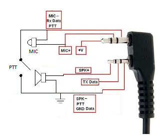
Here is the Microphone and external speaker connection details.

Both the modules is available from Giga Technology http://www.giga.co.za

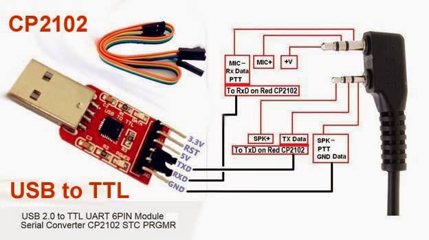
Programming cable assembly.

Programming cable assembly.


Programming your Baofeng radio (UV-5R?)

Frequency Mode vs. Channel Mode
These two modes have different functions and often confused. 

  • Frequency Mode - Used for a temporary frequency assignment, such as a test frequency or quick field programming. 
  • Channel Mode - Used for selecting preprogrammed channels. 

All programming MUST be initially done in the Frequency Mode using the Upper Display only. From there you have the option of assigning the entered data to a specific channel for later access in the Channel Mode if desired.

IMPORTANT: Programming done using the Lower display cannot be saved and will be lost.  


Programming a Repeater Channel with Standard Offsets (600kHz minus offset)
  
This example is for:  146.700 MHz
600kHz minus offset
into channel 99
CTCSS tone 123.0

1.    Set radio to VFO Mode   (Frequency Mode)
      a.)     UV5R series - Press VFO/MR button
      b.)     UV82 - Turn radio OFF, then Press/Hold MENU button during PowerON.

2.    Select   Display A    (this is a must)
      a.)     UV5R/GT3 - Press     [A/B]     and select the Upper Display.
      b.)     UV82 - Press [EXIT A/B] and select the Upper Display.

3.    Disable TDR (Dual Watch/Dual RX) which toggles between A and B.
          Press  [Menu]   7   [Menu]
          Select OFF
          Press  [Menu]   [Exit]

4.    Delete Prior Data from the channel to be programmed.
          Press  [Menu]   2 8   [Menu]
          Enter   9 9  (Memory Channel to clear)
          Press  [Menu]   [Exit]

5.    Enter the Repeater Offset.
         Press [Menu]   2 6   [Menu]
         Enter  0 0 6 0 0
         Press  [Menu]   [Exit]

6.   Enter the Transmit Frequency Shift.
        Press  [Menu]   2 5   [Menu]
        Enter  2 for Minus shift. ( or    to  - )
        Press  [Menu]   [Exit]  

7.   Set CTCSS or DCS codes for Transmit. 
         ( example = CTCSS TX tone 123.0 Hz )
            Press  [Menu]   1 3   [Menu]
            Enter  1 2 3 0   [Menu]   [Exit]

8.   Enter the repeater output frequency,  1 4 6 . 7 0 0 

9.   Store RX frequency
        Press  [Menu]   2 7   [Menu] 
        Enter   9 9  (Memory Channel)  ( 000 to 127 )    
            This is the channel that was cleared in step 4. 
        Press  [Menu]   [Exit] 

10.  Press the [ * Scan ] button.     
         This activates  Reverse Mode and displays the TX frequency.

11.   Press  [Menu]   2 7  [Menu] 
         Enter the same Memory Channel entered above. 
         Press  [Menu] 

12.   Press the  [* Scan] again to exit the Reverse Mode.

13.   Press  [Exit]

This will now appear it in the channel list when you switch to Channel Mode. (MR)
Boafeng UV-VF5 Circuit diagram

REF http://www.uv3r.com/images/Schematic-Baofeng-UV5R.pdf

Radio programing details
here is a link to the Chirp program http://chirp.danplanet.com

Which antenna is best?

 It's all personal preference, but a good rule of thumb is:
 The longer the radiator, the better the range, especially on transmit.
 Short stubby antennas use a coil to match TX to 50 ohm, not radiate.
 The closer to 1/4 wavelength in the air, the better the performance.

NOTE:
      A field test was performed between 31 popular antennas.
     The results can be found HERE.   

Receiving NOAA weather satellite images with a RTL dongle and a Turnstile crossed dipole automatically.

$
0
0
Receiving NOAA weather satellite images with a RTL dongle and a Turnstile crossed dipole automatically. 
NOAA19-HVCT 2017-03-18 15:40 Taken with this system
What do you need to setup a automatic NOAA APT Weather station configuration.
The necessary licences for your region. FCC ...
Here is a Link to Automated NOAA weather satellite System In Bassonia South Africa.


Hardware requirement diagram.

How dose this system work?

  • The system consists of 3 shell scripts that tai 5 applications together.
  • The shell scrip will fetch the satellite TLE keps data from celestrack. http://www.celestrak.com/NORAD/elements/weather.txt
  • The NOAA satellite TLE data is then passed to the predict satellite positioning software.
  • The predict software calculate when the next satellite will be above your radio station.
  • The result of the calculations for the next 24 hours is then send to a scheduler program call "at".
  • The "at" scheduler will then start and stop the rtl_fm receiver at the required time, frequency and record the audio in the recording directory from the NOAA satellite.
  • The Audio files is not in the correct format for wxtoimg utility to convert it to images and need to be converted to the correct format using the SOX until.
  • The converted recordings is then passed to wxtoimg utility to generate the Satellite images.
  • The images is then exposed via a Apache web server with a php plugin to the internet.

Hardware

  • Raspberry PI and power supply
  • RTL dongle with USB cable and MCX connector adaptor.
  • RG58 Coaxial cable with connectors or better cable. Max 4m
  • Turnstile crossed dipole Antenna.
  • All Hardware and software is available from Giga Technology

Software

  • Predict - Utility to calculate satellite azimuth and elevation using TLE Kep elements
  • rtl_fm - SDR fm Demodulation Utility to decode your ATP Satellite signal to audio file.
  • Sox - To convert row Audio file into format for wxtoimg to convert to Satellite Image.
  • Shell script to calculate the schedule for enabling the rtl receiver.
  • wxtoimg - Utility that converts ATP Audio files into Satellite Images.
  • Apache server to expose the images to the internet.
Software Functional Block diagram


The following software need to be installed on Raspberry Pi or Linux server.

sudo apt-get install predict
sudo apt-get install rtl-sdr
sudo apt-get install sox
sudo apt-get install wxtoimg
sudo apt-get install git
sudo apt-get install apache2
sudo apt-get install php
sudo apt-get install libapache2-mod-php
sudo apt-get install php-mcrypt
sudo apt-get install php-mysql

Create a directory sh in hour home directory.
cd
mkdir sh
cd sh
Create a wxsat directory in your home directory
cd
mkdir wxsat
cd wxsat
Create a images directory in wxsat directory
mkdir images
Create a recordings directory.
mkdir recordings
Create a thumb directory inside the images directory.
cd images
mkdir thumb


cd to sh directory and download the following scripts from github using the git command below
cd ~sh
git clone https://github.com/antonjan/noaa_weather.git
it will create a directory noaa_weather in the sh directory
Inside the directory there will be three scripts. (the index.php will need to be moved later)
noaa_sat_scheduler.sh
noaa_scheduler.sh
create_thumbnail.sh
index.php
Readme.me

You will need to change your stations GPS coordinates in the following files

Edit the file noaa_sat_schedule.sh and change the following details to your coordinates.
The last one is altitude in meters.

/usr/local/bin/wxmap -a -T "NOAA ${bird}" -H ~/wxsat/weather.txt -L "-26.17/-28.03/1700" -p0 -o "\$mapdate" ~/wxsat/noaa${bird}map.png
/usr/local/bin/wxmap -a -T "NOAA ${bird}" -H ~/wxsat/weather.txt -L "-26.17/-28.03/1700" -p0 -o "\$mapdate" ~/wxtoimg/maps/noaa${bird}map.png

and save the file.
Then you need update the predict program with your station coordinates.
Run the command sudo predict
Select the G to change your ground station position details.
and enter to get to next position. ESC to exit. ant then Q to exit.


Setup crontab to run the scrip at midnight
using the command sudo crontab -e
add the following at the bottom of the crontab file

1 0 * * * ~/sh/noaa_weather/noaa_scheduler.sh

You can run the script manually now to see if it works.
sudo ~sh/noaa_weather/noaa_scheduler.sh
it should create schedules to run for the next 24 hours.
type the command sudo at -l witch should list the scheduled tasks
You should see something like this.
94Thu Mar 23 02:13:00 2017 a root
95Thu Mar 23 14:43:00 2017 a root
88Thu Mar 23 05:30:00 2017 a root
92Thu Mar 23 05:49:00 2017 a root
89Thu Mar 23 17:53:00 2017 a root

There also should be at least 4 files in the ~/wxsat directory

noaa15.at
noaa18.at
noaa19.at
weather.txt

If you got here all went ok.
Connect the rtl dongle to your raspberry pi or Linux (ubuntu) computer.
Connect the coaxial cable to the Turnstile crossed dipole at wate for the first scheduled task as in the list above. sudo at -l

If you want to remove a previous task you can run the following command.
Make sure you always only have one task for the same time.
sudo atrm [task number]   EG sudo atrm 94

Go and look in the ~/wxsat/images  directory and your satellite images should be there for the day.
cd ~/wxsat/images

Ok now we need to get your image exposed on the Apache2 web server.

You now will need the full path to your wxsat directory.
cd ~/wxsat
pwd
/home/anton/wxsat
So in my case the full path is /home/anton/wxsat
Create a link between the apache server and you images.
go to directory /var/www
cd /var/www
sudo ln -s /home/anton/wxsat ./wxsat

if you goto you webserver on raspberry or linux you should see your images.
Take your browser on the Raspberry or linux server and goto http://localhost/wxsat/images
You will see a directory with file names of all the satellite images.
If you cant see the images you might have to make a small change to your apache2.conf file.

make sure you have the following in you /etc/apache2/apache2.conf file
change or add this

<Directory /var/www/>
        Options Indexes FollowSymLinks
        AllowOverride None
        Require all granted
</Directory>

Then restart Apache2
sudo systemctl restart apache2


Image file list

Ok So you want to see thumbnail images and the click on image to view full image the copy the file index.php from the git repository into your images directory.
cp ~/sh/noaa_weather/index.php ~/wxsat/images/

Ok check your image directory in your web browser again and it should now have index page with thumbnails. You can change the index.php content of this page to add your details.

http://localhost/wxsat/images

Thumbnail Image index page


Here is a Link to Automated NOAA weather satellite System In Bassonia South Africa.

My Satellite Antennas


Configuring my wifi dongle on the Raspberry Pi to connect to my network router.

$
0
0
Configuring my wifi dongle on the Raspberry Pi to connect to my network router.

Generic Wifi dongle used on my Raspberry Pi


I had to get my router details and had to configure the following configuration files.
I wanted to give my Raspberry Pi a spear static IP so I always know what it is on my network.

I edited the following files.

/etc/wpa_supplicant/wpa_supplicant.conf

I added the following at the end. I was using WEB encryption and shared key on my router.
Change the details in yellow for your router if you use web encryption with shared key.
use your favorite editor
sudo vi /etc/wpa_supplicant/wpa_supplicant.conf

#Configeration of the file /etc/wpa_supplicant/wpa_supplicant.conf
country=GB
ctrl_interface=DIR=/var/run/wpa_supplicant GROUP=netdev
update_config=1
network={
        ssid="MyRouter" # your router ID
        key_mgmt=NONE
        wep_key0="0123456789123" # or 13 characters, or a hexkey starting with 0x your key
        wep_tx_keyidx=0
        auth_alg=OPEN
}

Save and exit
And the change the following file

Edit the file as follows in the section configuring wlan0
I gave my Raspberry pi a spear static Ip on my network so always now what the ip is and don't use DHCP so I will not know what the Ip will be 
use your favorite editor

sudo vi /etc/network/interfaces
auto wlan0
allow-hotplug wlan0
#iface wlan0 inet dhcp
iface wlan0 inet static
address 192.168.1.205  #Static Ip
netmask 255.255.255.0 # Ip mask of network
gateway 192.168.1.254 # IP gateway of router
wpa-conf /etc/wpa_supplicant/wpa_supplicant.conf
iface default inet dhcp

Save

And reboot Raspberry Pi sudo shutdown -r 0

ping your new Ip on Wifi network

ping 192.168.1.205

And it should now work.


Configuring my SA9227 with PCM5102A 32BIT / 384KHZ USB3 Hifi Audio DAC on Linux

$
0
0
Configuring my SA9227 with PCM5102A 32BIT / 384KHZ USB3 Hifi Audio DAC on Linux


SA9227 with PCM5102A 32BIT / 384KHZ USB3 Hifi Audio DAC 
I was looking for a high end Audio DAC for Linux and found this unit. I wanted to generate IQ moderation for a transmitter and this module would work nicely. It Unfortunately it only works on USB3 so this one cant be used on raspberry Pi 3 :-( but works fine on my Ubuntu laptop.


Description

  • Input :5 V (USB supply),
  • THD+N: <0.005% (RL = 10 kω)
  • independence: >95 dB
  • DRC: >95 dB
  • USB sample rate:16-32BIT/32-284KHZ
I first tried it on a USB 2 port but got this error when connecting the Device to the usb2 port

/var/log$ tail -f syslog
Jun  5 21:32:03 anton-SATELLITE-P755 kernel: [101544.064132] usb 2-1.2: device descriptor read/64, error -32
Jun  5 21:32:03 anton-SATELLITE-P755 kernel: [101544.240155] usb 2-1.2: new full-speed USB device number 21 using ehci-pci
Jun  5 21:32:03 anton-SATELLITE-P755 kernel: [101544.312119] usb 2-1.2: device descriptor read/64, error -32
Jun  5 21:32:03 anton-SATELLITE-P755 kernel: [101544.488089] usb 2-1.2: device descriptor read/64, error -32
Jun  5 21:32:04 anton-SATELLITE-P755 kernel: [101544.664066] usb 2-1.2: new full-speed USB device number 22 using ehci-pci
Jun  5 21:32:04 anton-SATELLITE-P755 kernel: [101545.072135] usb 2-1.2: device not accepting address 22, error -32
Jun  5 21:32:04 anton-SATELLITE-P755 kernel: [101545.144111] usb 2-1.2: new full-speed USB device number 23 using ehci-pci
Jun  5 21:32:05 anton-SATELLITE-P755 kernel: [101545.552096] usb 2-1.2: device not accepting address 23, error -32
Jun  5 21:32:05 anton-SATELLITE-P755 kernel: [101545.552269] usb 2-1-port2: unable to enumerate USB device
Jun  5 21:32:05 anton-SATELLITE-P755 gnome-session[2394]: (gnome-software:2545): Gs-WARNING **: failed to call gs_plugin_refine on appstream: Error opening file: Permission denied


I then tried it on a usb 3 port  and got the following log.

Jun  5 21:49:55 anton-SATELLITE-P755 kernel: [102616.072168] usb 3-1: new full-speed USB device number 2 using xhci_hcd
Jun  5 21:49:55 anton-SATELLITE-P755 kernel: [102616.192175] usb 3-1: device descriptor read/64, error -71
Jun  5 21:49:55 anton-SATELLITE-P755 kernel: [102616.416205] usb 3-1: device descriptor read/64, error -71
Jun  5 21:49:56 anton-SATELLITE-P755 kernel: [102616.632092] usb 3-1: new full-speed USB device number 3 using xhci_hcd
Jun  5 21:49:56 anton-SATELLITE-P755 kernel: [102616.752241] usb 3-1: device descriptor read/64, error -71
Jun  5 21:49:56 anton-SATELLITE-P755 kernel: [102616.976267] usb 3-1: device descriptor read/64, error -71
Jun  5 21:49:56 anton-SATELLITE-P755 kernel: [102617.192119] usb 3-1: new full-speed USB device number 4 using xhci_hcd
Jun  5 21:49:56 anton-SATELLITE-P755 kernel: [102617.192513] usb 3-1: Device not responding to setup address.
Jun  5 21:49:56 anton-SATELLITE-P755 kernel: [102617.396397] usb 3-1: Device not responding to setup address.
Jun  5 21:49:57 anton-SATELLITE-P755 kernel: [102617.600038] usb 3-1: device not accepting address 4, error -71
Jun  5 21:49:57 anton-SATELLITE-P755 kernel: [102617.712114] usb 3-1: new high-speed USB device number 5 using xhci_hcd
Jun  5 21:49:57 anton-SATELLITE-P755 kernel: [102617.733859] usb 3-1: New USB device found, idVendor=262a, idProduct=9227
Jun  5 21:49:57 anton-SATELLITE-P755 kernel: [102617.733864] usb 3-1: New USB device strings: Mfr=1, Product=2, SerialNumber=0
Jun  5 21:49:57 anton-SATELLITE-P755 kernel: [102617.733867] usb 3-1: Product: HD USB Audio
Jun  5 21:49:57 anton-SATELLITE-P755 kernel: [102617.733869] usb 3-1: Manufacturer: XENRAN Audio
Jun  5 21:49:57 anton-SATELLITE-P755 kernel: [102617.737019] input: XENRAN Audio HD USB Audio as /devices/pci0000:00/0000:00:1c.5/0000:05:00.0/usb3/3-1/3-1:1.0/0003:262A:9227.0002/input/input16
Jun  5 21:49:57 anton-SATELLITE-P755 kernel: [102617.737332] hid-generic 0003:262A:9227.0002: input,hidraw0: USB HID v1.00 Device [XENRAN Audio HD USB Audio] on usb-0000:05:00.0-1/input0
Jun  5 21:49:57 anton-SATELLITE-P755 mtp-probe: checking bus 3, device 5: "/sys/devices/pci0000:00/0000:00:1c.5/0000:05:00.0/usb3/3-1"
Jun  5 21:49:57 anton-SATELLITE-P755 mtp-probe: bus: 3, device: 5 was not an MTP device
Jun  5 21:49:57 anton-SATELLITE-P755 systemd-udevd[19211]: Process '/usr/sbin/alsactl -E HOME=/run/alsa restore 1' failed with exit code 99.
Jun  5 21:50:01 anton-SATELLITE-P755 gnome-session[2394]: (gnome-software:2545): Gs-WARNING **: failed to call gs_plugin_refine on appstream: Error opening file: Permission denied


This looked promising

I then checked if Alsa would see the device

sudo aplay -l
**** List of PLAYBACK Hardware Devices ****
card 0: PCH [HDA Intel PCH], device 0: ALC269VB Analog [ALC269VB Analog]
  Subdevices: 1/1
  Subdevice #0: subdevice #0
card 0: PCH [HDA Intel PCH], device 3: HDMI 0 [HDMI 0]
  Subdevices: 1/1
  Subdevice #0: subdevice #0
card 1: Audio [HD USB Audio], device 0: USB Audio [USB Audio]
  Subdevices: 0/1
  Subdevice #0: subdevice #0
card 1: Audio [HD USB Audio], device 1: USB Audio [USB Audio #1]
  Subdevices: 1/1
  Subdevice #0: subdevice #0

and the yellow was added as a new device to be used.

I could now use the normal Alsa audio controls with this device.

RF Noise Monitoring system for HF

$
0
0

RF Noise Monitoring system on a Raspberry Pi

(This system will record RF signals and upload the results to the Server where trending graphs are created)

This system software is available pre installed on a 16GB SD card from Giga Technology
Raspberry Pi OS with HF monitoring software pre installed
What do I get on the software?
I system that will record 1Mhz band with sapless every 2 minutes generating Graphs and Heat-map of the hole 1 to 30Mhz band.
What hardware do I need?
The  100khz to 1.7Ghz HF dongle as in picture below Screenshot of Graph monitoring.
url of link on system http://localhost/hf_noise/graph/1Mhz_Power.php
Link to live system is here http://zr6aic.giga.co.za/hf_noise/graph/1Mhz_Power.php 
Screenshot of the HF Monitoring system

How dose this system work

Block diagram of the HF Monitoring system

How dose the HF Noise Monitoring system work

  • The HF noise monitoring system takes a 1Mhz bandwidth samples every 2 minutes using the rtl_power utility and save the measurements in a CVS fie.
  • The 2 minute scheduling is done with a Crontab calling a script in the hf_noise directory.
  • The RF Samples is taken at a 1Mhz bandwidth from 1M to 30Mhz therefore 29 of  the CVS files is created and gets appended as the measurements is made.
  • A Perl script utility is the executed from a cron scedular  to read the 29 CSV files and import there data into a RRD database.
  • The RRD database then gets interrogated by another Perl script scheduled by a cronjob to generate the graph Images and and html files and get saved in the Apache web server graph directory witch is the exposed on http://localhost/hf_noise/graph/1Mhz_Power.php
  • Link to Live system http://zr6aic.giga.co.za/hf_noise/graph/1Mhz_Power.php 
  • The RRD database will then create the Hourly, Daily,Weekly,Monthly and Yearly averages and   then generates the graphs every 2 minutes according to the parameters passed to Database.
  • The generated graphs is then displayed in a php page via a Apache web server with an php plugin on the following url http://localhost/hf_noise/graph/1Mhz_Power.php.
  • Trends can then be seen on a graphs over time.
  • The heat map is generated by a python script from different CSV files and is saved in the /var/www/hf_noise/images directory and can be accessed on the local web server on the following url http://localhost/hf_noise/images
  • Link to live system http://zr6aic.giga.co.za/vhf_heatmap/images/

Here is a list of RRD database management tips

  • How to backup my RRD db data?
  • use rrdtool dump hf_noise.rrd > filename.xml to export the data to XML format.
  • How to Restore my RRD db data?
  • Transfer the XML dump to the target system. Run rrdtool restore [--range-check|-r] [--force-overwrite|-f] filename.xml filename.rrd to create a new RRD from the XML dump. See rrdrestore for details.
  • How to change some of the the RRD db data?
  • Use rrdtool dump to export RRD files to XML.
    Open the XML file, find and edit the bad data.
    Restore the RRD file using rrdtool restore.

 How to generate a brand new RRD db?


There is an script in the hf_noise directory called create_rrd_db.sh
You can just run this script in the hf_directory sudo ./create_rrd_db.sh

Here is the details of the scrip.
    rrdtool create  hf_noise.rrd --start now-2d --step 120 DS:1Mhz_Power:GAUGE:120:-40:10 DS:2Mhz_Power:GAUGE:120:-40:10 DS:3Mhz_Power:GAUGE:120:-40:10 DS:4Mhz_Power:GAUGE:120:-40:10 DS:5Mhz_Power:GAUGE:120:-40:10 DS:6Mhz_Power:GAUGE:120:-40:10 DS:7Mhz_Power:GAUGE:120:-40:10 DS:8Mhz_Power:GAUGE:120:-40:10 DS:9Mhz_Power:GAUGE:120:-40:10 DS:10Mhz_Power:GAUGE:120:-40:10 DS:11Mhz_Power:GAUGE:120:-40:10 DS:12Mhz_Power:GAUGE:120:-40:10 DS:13Mhz_Power:GAUGE:120:-40:10 DS:14Mhz_Power:GAUGE:120:-40:10 DS:15Mhz_Power:GAUGE:120:-40:10 DS:16Mhz_Power:GAUGE:120:-40:10 DS:17Mhz_Power:GAUGE:120:-40:10 DS:18Mhz_Power:GAUGE:120:-40:10 DS:19Mhz_Power:GAUGE:120:-40:10 DS:20Mhz_Power:GAUGE:120:-40:10 DS:21Mhz_Power:GAUGE:120:-40:10 DS:22Mhz_Power:GAUGE:120:-40:10 DS:23Mhz_Power:GAUGE:120:-40:10 DS:24Mhz_Power:GAUGE:120:-40:10 DS:25Mhz_Power:GAUGE:120:-40:10 DS:26Mhz_Power:GAUGE:120:-40:10 DS:27Mhz_Power:GAUGE:120:-40:10 DS:28Mhz_Power:GAUGE:120:-40:10 DS:29Mhz_Power:GAUGE:120:-40:10 DS:30Mhz_Power:GAUGE:120:-40:10 RRA:AVERAGE:0.5:1:864000 RRA:AVERAGE:0.5:60:129600 RRA:AVERAGE:0.5:3600:13392 RRA:AVERAGE:0.5:86400:3660

I have still got my csv files and want to reload it into my rrd database

Still need to add details how to do this.


HF Heat map monitoring System.  http://localhost/hf_noise/images 

link to live system http://zr6aic.giga.co.za/hf_noise/images/
Here is  a screenshot of the monitoring page and the green button
 can be used to select the frequency band of interest


Single view

Here is a view of the HF spectrum from 1Mhz to 30Mhz (activity can now be seen for the day)
Here is a view of the heat map that was selected
If you click on the image the the image will zoomed to maximum

Enlarged View

Here is a screenshot of the enlarged view.

So here is an example of the utility that generate the CSV file

Noise Recording

rtl_power -f 24M:1.7G:1M -g 50 -i 20m -1 noise-unmodded.csv

Heat map Plotting.

Still need to add detail


Installing the system from scratch (not yet complete)

sudo apt-get install cpanminus

sudo cpanm Text::Trim
sudo cpanm  Text::CSV
sudo cpanm  Date::Manip

sudo cpanm Text::Trim qw(trim)
sudo cpanm RRD::Simple ()

rrdtool update hf_noise.rrd ds-name:30Mhz_Power $recordtime:$rrdfields[29]\n";


rrdtool create  hf_noise.rrd --start now-2d --step 120 DS:1Mhz_Power:GAUGE:120:-40:10 DS:2Mhz_Power:GAUGE:120:-40:10 DS:3Mhz_Power:GAUGE:120:-40:10 DS:4Mhz_Power:GAUGE:120:-40:10 DS:5Mhz_Power:GAUGE:120:-40:10 DS:6Mhz_Power:GAUGE:120:-40:10 DS:7Mhz_Power:GAUGE:120:-40:10 DS:8Mhz_Power:GAUGE:120:-40:10 DS:9Mhz_Power:GAUGE:120:-40:10 DS:10Mhz_Power:GAUGE:120:-40:10 DS:11Mhz_Power:GAUGE:120:-40:10 DS:12Mhz_Power:GAUGE:120:-40:10 DS:13Mhz_Power:GAUGE:120:-40:10 DS:14Mhz_Power:GAUGE:120:-40:10 DS:15Mhz_Power:GAUGE:120:-40:10 DS:16Mhz_Power:GAUGE:120:-40:10 DS:17Mhz_Power:GAUGE:120:-40:10 DS:18Mhz_Power:GAUGE:120:-40:10 DS:19Mhz_Power:GAUGE:120:-40:10 DS:20Mhz_Power:GAUGE:120:-40:10 DS:21Mhz_Power:GAUGE:120:-40:10 DS:22Mhz_Power:GAUGE:120:-40:10 DS:23Mhz_Power:GAUGE:120:-40:10 DS:24Mhz_Power:GAUGE:120:-40:10 DS:25Mhz_Power:GAUGE:120:-40:10 DS:26Mhz_Power:GAUGE:120:-40:10 DS:27Mhz_Power:GAUGE:120:-40:10 DS:28Mhz_Power:GAUGE:120:-40:10 DS:29Mhz_Power:GAUGE:120:-40:10 DS:30Mhz_Power:GAUGE:120:-40:10 RRA:AVERAGE:0.5:1:864000 RRA:AVERAGE:0.5:60:129600 RRA:AVERAGE:0.5:3600:13392 RRA:AVERAGE:0.5:86400:3660


sudo apt-get install librrds-perl
sudo apt-get install rrdtool
perl -MCPAN -e 'install Test::Deep'
perl -MCPAN -e 'install Test::Pod'
perl -MCPAN -e 'install Test::Pod::Coverage'
perl -MCPAN -e 'install RRD::Simple'

Still need to add details


Viewing all 69 articles
Browse latest View live